ESP32 Configurator
Project Overview
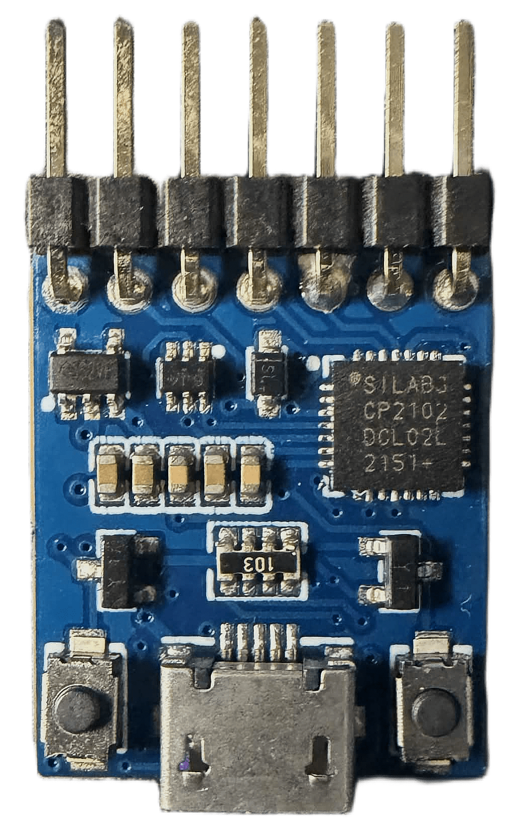
The ESP32 Configurator is a dedicated PCB designed to interface with ESP32 modules through their UART-based ROM bootloader. The design features a Silicon Labs CP2102 USB-to-UART bridge, automatic EN and IO0 control circuitry for bootloader entry, and status indication LEDs for power and serial activity.
Developed before native USB interfaces became common on newer ESP32 devices, the board automates the reset and boot mode sequencing required for firmware programming, reducing the need for manual intervention during flashing.
ESP32 Configurator PCB
Hardware Design
Implementation Notes
The programming interface is implemented using a CP2102 USB-to-UART bridge connected to the ESP32 serial bootloader pins. EN and IO0 control signals are routed through dedicated circuitry to generate the boot mode transitions required for firmware upload.
The board was designed as a reusable programming tool for custom ESP32 hardware. By separating the USB-to-UART interface and bootloader control circuitry from the target device, future ESP32 designs can be programmed without requiring an onboard USB interface or dedicated programming hardware.
As my first PCB design, the project contains schematic notation and documentation conventions that differ from my current design practices.
Revision Notes
A hardware revision is not planned for this project, as native USB programming has largely removed the need for a dedicated ESP32 programming board in my current workflow. During testing, it was identified that a 10 kΩ pull-up resistor on the ESP32 EN signal is required for correct automatic reset operation. This pull-up must be present on the target ESP32 board for the configurator’s auto-reset sequence to function properly; otherwise, manual reset can be used during programming. The requirement can be satisfied either on the target board or by incorporating the pull-up into a future revision of the configurator PCB.