Junior Design Range Finder
Project Overview
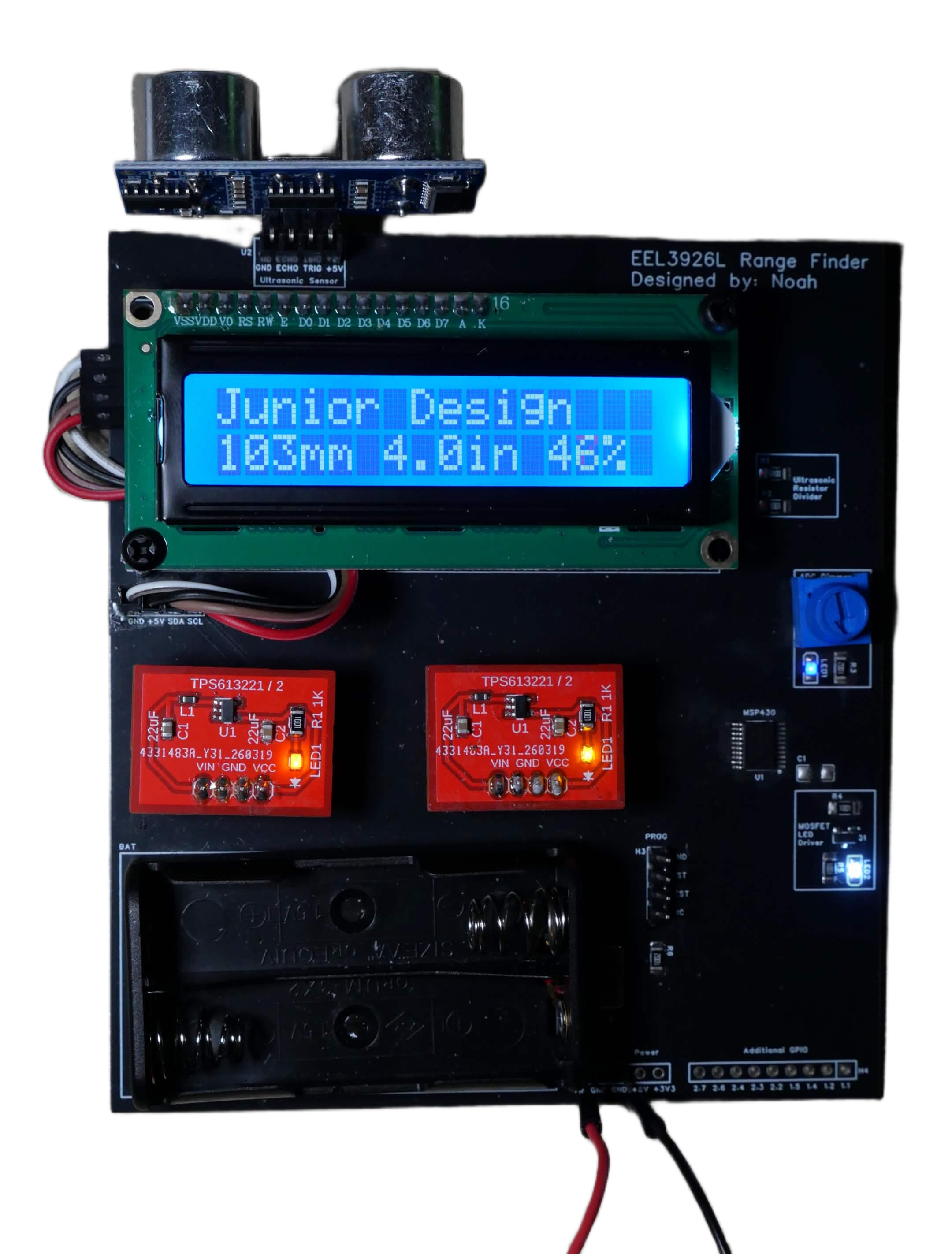
This range finder PCB was created for my junior design course. The board combines ultrasonic distance sensing, analog input processing, PWM output control, and an I2C LCD interface into one embedded hardware project.
The system reads an ultrasonic sensor for distance measurement and uses an ADC potentiometer input to control LED brightness through PWM. A MOSFET LED driver handles the higher-current LED output, while the LCD displays both the measured range and the potentiometer percentage.
Assembled Range Finder
Hardware Design
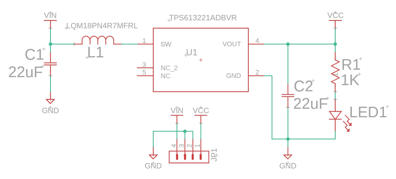
Power Regulation
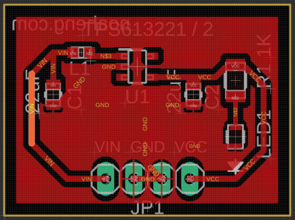
The regulator design supports the range finder hardware by providing stable power. Two instances of the PCB were used on the range finder with different voltage outputs.
Regulator Schematic
Regulator PCB
Firmware Behavior
The firmware reads the ultrasonic sensor to calculate distance and samples the potentiometer through the microcontroller ADC. The potentiometer value is converted into a percentage for the LCD and into a PWM duty cycle for LED brightness control.
The LCD provides live feedback by showing the ultrasonic sensor reading alongside the potentiometer percentage, making the board simple to test and demonstrate.